

The OOSE method described in the book Object-Oriented Software Engineering - A use Case Driven Approach [3] by Ivar Jacobson et al. has a number of contributions which are relevant for a discussion of dynamic OOD models.
The central concept in the book is use cases. A use case is a scenario which involves the computer system and a number actors (users and external computer systems). Thus, a use case describes the borderline between the forthcoming computer system and the surrounding world in terms of the interaction between the system and the actors. A number of use cases, which cover the problem domain, are formulated early in the OOA and OOD process, during a requirement gathering phase. The use cases are stated informally, in plain text and use cases can be specialized/generalized and extended in various ways. In the subsequent design steps the use cases are basis for the majority of the further developments, such as finding the objects (classes) and operations.
In the design phase of the construction process the use cases are turned into interaction diagrams, in which objects (called blocks in OOSE) send messages (called stimuli in OOSE) to each other. The temporal relations among the message passings can be seen from the interaction diagrams. In addition the interaction diagrams can be related to pieces of pseudo program, which realizes the interaction.
Figure 11 shows an example of an interaction diagram. The diagram is reproduced directly from (the upper part of) figure 8.11 of [3].
The example is a recycling machine for bottles, cans and crates. When the user of the machine deposits an item (such as a bottle) the machine first checks whether the item is acceptable. If it is, the machines increments a counter which keeps track of this particular kind of item. In addition it increments a counter which keeps track of the total number of items received, again specific to each possible kind of item. All this makes up the basis for printing a receipt to the customer.
The interaction diagram in figure 11 involves four objects: A customer panel (which is an interface object in OOSE terms), a Deposit item receiver (which is a control object), a Receipt basis and a Deposit item (both entity objects). Each `Deposit item' object contains information about (1) the value of the item, (2) the total number received this day, and (3) the physical characteristics of the item. A `Receipt basis' object is able to count how many items of each kind the customers has deposited. From the diagram and the pseudo code we see that it is first checked whether the deposited item is acceptable. If it is acceptable, it is inserted into the Receipt basis object, and its counter is incremented.
There are several things to notice in the interaction diagram from above:
In the solution which we adopt for this paper there are two central objects:
Objects of type ITEM_SET can be used to keep track of the individual
customer's record (CUSTOMER_TOTAL) as well as to administer the total
number of items (GRAND_TOTAL) of each particular kind, which is
returned during a day.
In figure 12 we show a trace of our representation of the recycling example from above. Recall that such a trace shows an extract of the information in an underlying tree structure. As can be seen from the figure, five different global objects are provided initially. The interesting messages is `deposit-item', which takes some description of the deposited item as a parameter. We first check whether the item is acceptable, by sending the message does-exist? to the object ACCEPTABLE_ITEMS. We assume that this operation returns the relevant item object, if the description of the item matches an item object from the acceptable items. In turn, this item is inserted into the CUSTOMER-TOTAL object. Next an item counter in the CUSTOMER-TOTAL object is incremented. Finally the GRAND-TOTAL object is incremented with respect to the item.
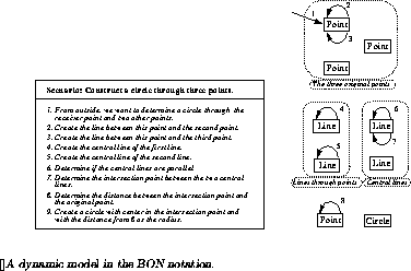
In section 5.1 we showed how the circle construction through three given points could be described in Nerson's and Waldén's BON notation. Although the circle construction example probably is far away from the typical problems supposed to be attacked in OOSE, we will also sketch an OOSE interaction diagram for the circle construction problem. The result is shown in figure 13.
One of the main difficulties is to illustrate how objects are created dynamically during the course of the interaction. Neither of Line1, Line2 and the central lines exist when Circle-on-points operation is called; they are all created as temporary objects during the execution of the operation. Similarly it is awkward to illustrate how objects are passed as parameters to operations. As a consequence it is difficult to make a good correspondence between the pseudo-program in figure 13 and the interaction diagram proper. Notice that these weaknesses basicly are the same as those identified with the BON notation in section 5.1.


